|
|
DISROC Gallery |
|
| DISROC2D - Example: |
Other Examples |
Crack propagation around an inclusion due to thermal expansion
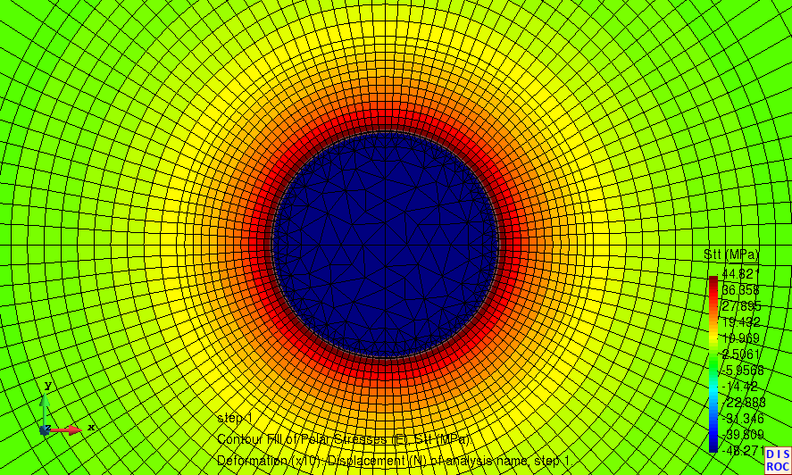
A circular inclusion in an infinite medium undergoes a thermal expansion (Figure 1a). This creates isotropic compression
in the inclusion (srr=sqq=-48.27 MPa)
and tensile stresses of up to sqq=44.82MPa) in the surrounding matrix
(Figure 1b for the sqq stress).
Figure 1 : (a) Circular inclusion in an infinite matrix undergoing thermal expansion,
(b) Compression in the inclusion and tensile stress sqq
in the surounding matrix
When the tensile stress in the matrix exceeds its tensile strength, cracks appear and begin to propagate in the matrix.
These cracks are radial (Figure 2). The constitutive model used for the joint elements allowing to simulate this fracture
propagation was the CZFrac model in Disroc(See the Materials Catalogue).
This Cohesive Zone model has been the subject of numerous validation works based on comparison with the solutions given by
the Linear Fracture Mechanics.
Then, the temperature in the inclusion decreases and the radial cracks begin to close (Figure 4).
This continues until complete closure of the radial cracks and zero stress in the inclusion (Figure 5)
Then, the cooling of the inclusion continues and generates tensile stresses on the inclusion-matrix interface. When these
stresses exceed the tensile strength of the interface, circumferential cracks around the inclusion appear.
If the interface has elastoplastic behavior (Model 21120 in Disroc Materials Catalogue),
the separation opening is regular (Figure 6). But when the behavior of the
interface corresponds to brittle damage (CZFrac model in Disroc), the separation at the interface goes
through a less regular process of progressive rupture of bonding bridges and finally some bridges remain (Figure 7).
The whole heating-cooling process with the induced damage can be seen in the following video. There are three phases; first the
phase of heating the inclusion with radial cracks induced in the matrix, then the cooling of the inclusion to the initial
temperature causing the radial cracks closure, and finally further cooling of the inclusion inducing debonding at the
interface (Click on the image to see the video).
Note that the model contains 18,952 nodes and 14,742 elements and the computation time for the entire process including the
thermal expansion and cracking phase, the cooling and crack closure phase and then the first stages of the debonding phase shown in Figure 7, on the
interface, on a laptop equipped with an Intel processor, i7, 3.00GHz, is less than 15 minutes. At least 10% of this time is
used for video recording (100 recordings to have 100 images for a phase) and the computation time would therefore be less if
only the final results were needed.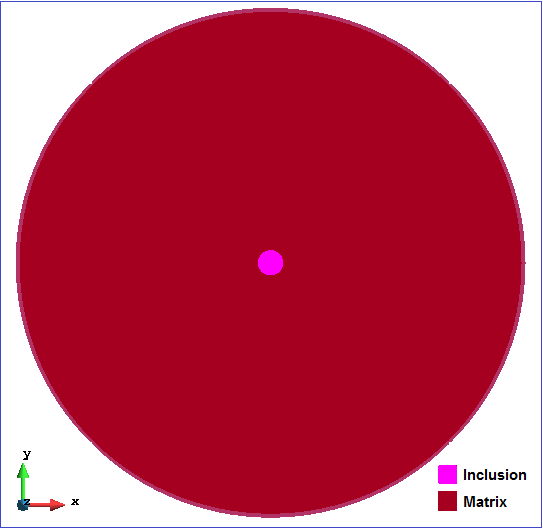
 (a) (b)
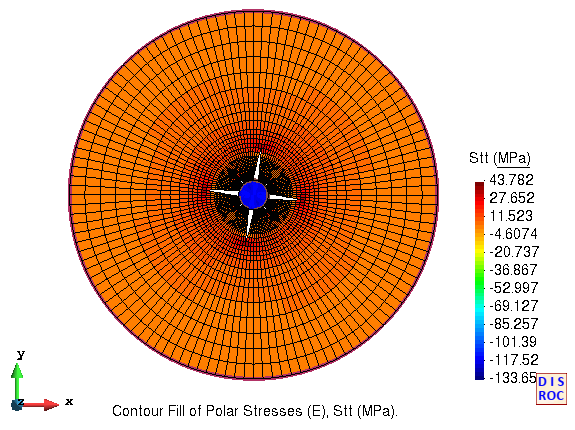
Figure 2 : Radial cracks around the inclusion
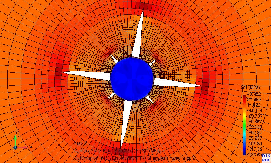
Figure 3 : Radial cracks around the inclusion (details) 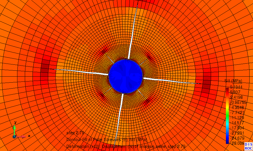
Figure 4 : Closure of radial craks due to the cooling of the inclusion
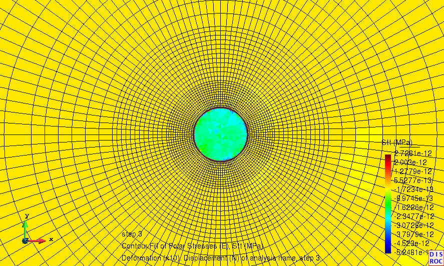
Figure 5 : Return to the zero stress state in the inclusion. Radial cracks exist in the matrix but are completely closed.
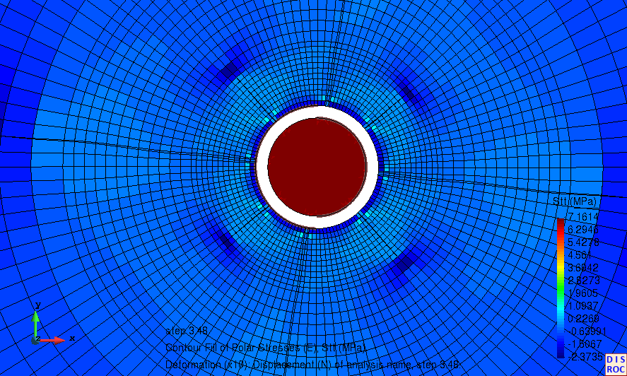
Figure 6: Debonding at the interface due to the cooling of the inclusion modeled by an elastoplastic model
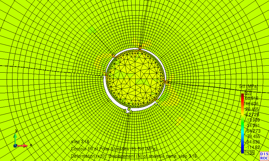
Figure 7 : Debonding at the interface due to the cooling of the inclusion modelled by a brittle damage model
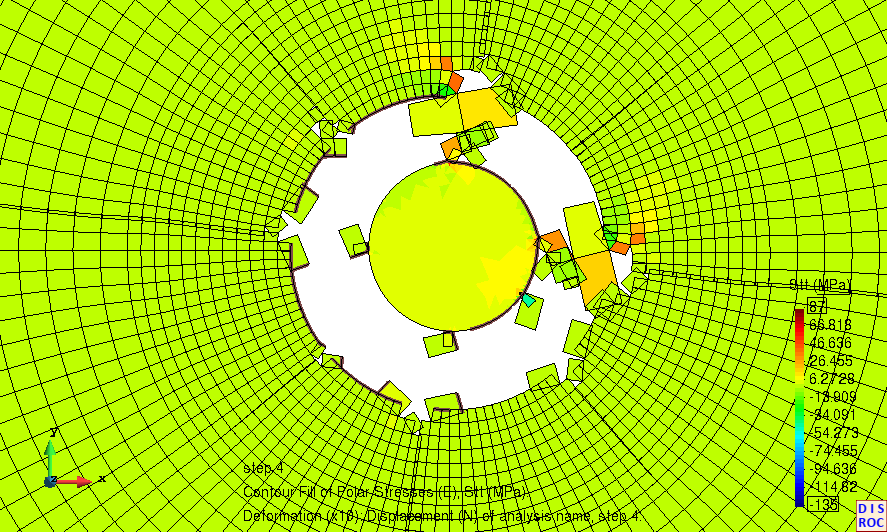
Figure 8 : Advanced stage of debonding at the interface due to the cooling of the inclusion modelled by damage model
(Click on the image to see the video of the whole heating-cooling process)
This performance is due to the efficiency of the Finite Element Analysis method for
quasi-static processes used in Disroc and to advanced calculation algorithms developed in this code.