|
|
DISROC Examples |
|
| DISROC 5 - Example: |
Other Examples |
Safety Factor Calculation:
Shear Reduction Factor Method
The safetey factor for slope stability can be calculated by Disroc in different ways.
For fractures for
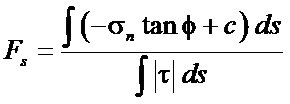
which the constitutive model includes cohesion and friction angle parameters, Disroc can calculate the ratio between the integral of shear
stress and of the maximum admissible shear on a slip surface. This maximum admissible shear is function of the normal stress,
friction angle and the cohesion. The safety factor is the inverse of this ratio:
Safety Factor |
This is the first method and it is efficient when there is only one potential slip surface. When multiple fractures fractures or
slip surfaces are
present in the model Disroc can calculate the integrals of shear and normal stresses and the corresponding safety factors separately
for each surface or each group of surfaces designated by the same material name. The details of stresses on the Joint Element
concerned by this calculation is given in the output file. Therefore if, for instance, the stability of a rock bloc implies
simultaneous slip on several surfaces, the user can calculate easily suitable combinations of stresses on different fractures .
The second method is the Shear Strength Reduction Method which is suitable for more general cases. The method consists in decreasing
all the cohesions and friction angles of the Mohr-Coulomb type materials by the same reduction factor, i.e., dividing them by a
number F greater than 1. The maximum value of F for which an equilibrium is possible, i.e. the code can calculate a solution of
stress and displacements for the applied loads on the structure, is designated the Safety Factor.
These two methods are illustrated in the following example for the excavation of an underground cavity in fractured granite
The Fig1.a shows the Finite Element model of the rockmass before excavation with three fracture lines designated Fracture1, Fracture2 and
Fracture3. Fig. 1.b shows the boundary conditions applied in order to create the initial state of the ground stresses:
a vertical stress sigma_yy applied on the upper boundary and a horizontal stress sigma_xx with a gradient in the vertical direction
applied on lateral sides. The weight action is also introduced as volume forces in the model.
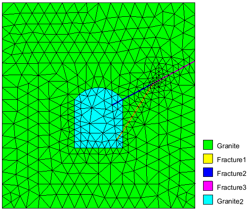 Fig.1a: Rockmass with fractures AAAAAAAAAAA
|
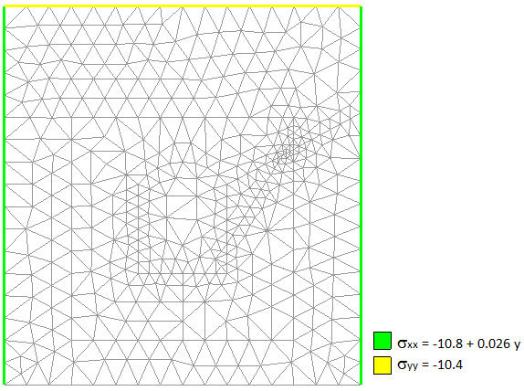 Fig.1b: FEM mesh with boundary conditions AAAAAAAAAAA
|
The Fig. 2a displays the vertical stress in the rockmass around the tunnel before excavation and the Fig.2.b, the boundary forces on the cavity wall applied by the material to be excavated. The excavation action consists in decreasing these forces to zero. This action is applied in 10 load steps.
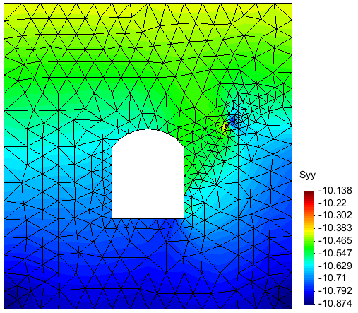 Fig.2a: Contour of Sigma_yy before excavation/span>
|
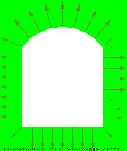 Fig.2b: Excavation forces
|
The Fig. 3a displays the final vertical stress in the rockmass after the excavation and the Fig.3.b, the deformed shape of the tunnel after excavation.
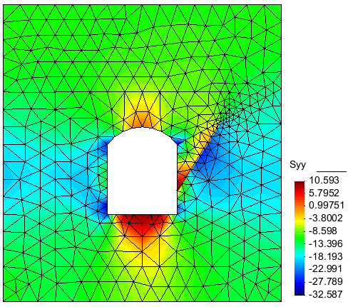 Fig.3a: Contour of Sigma_yy after excavation/span>
|
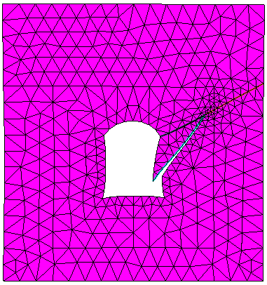 Fig.3b: Deformed geometry after excavation (displacement x 200)
|
First Method
The safety factor calculated at the final stage of excavation for the fractures 1,2,3 is presented in the following table.
This factor is 1.586 for Fracture1, 6.065 for Fracture2 and 18.926 for Fracture3. The details of the calculation are given
for each fracture: the joint elements numbers, their length and shear and normal stresses.
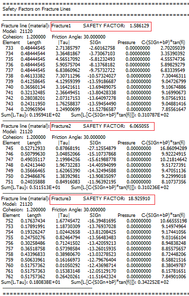
Figure 4: Safty factor calculated for the 3 fractures |
However, it is clear that the instability of the triangular block is determined by the slip on Fracture1 and Fracture 2 simultaneously and Fracture3 is not involved. For this reason, the above equation defining the factor of safety mus be applied to the global {Fracture1,Fracture2} system: the normal and shear stresses are integrated along these two fractures to calculate the safety factor. This calculation is performed by Excel software using the standard Disroc outpout data (Fig. 4). The result is given in Fig. 5: the shear and normal stresses on the two fractures 1 and 2 is to calculate their safety factors (in yellow) are combined to calulate the global safety factor which is found to be 2.51 (in blue).
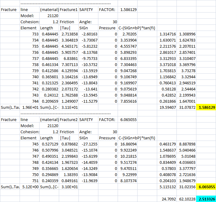
Figure 5: Combined Safety Factor calculated for the fractures 1 and 2 determining the stability of the triangular bloc |
Second Method: Shear Strength Reduction Method (SRM)
The second method consists in using the Disroc function "Shear Strength Reduction Method" in "Load Parameters" (Fig. 6).
In this example the reduction factor is assigned to vary from 2.0 to 3.0 in 5 intervals (increment of 0.2).
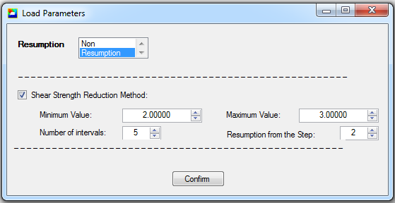
Figure 6: Shear Strength Reduction Method as a special loading function in Disroc |
The displacement of a characteristic point is considered as indicator of slip. The bottom point of the triangular bloc in Fig.3b
has the most significant displacement and is considered as the indicator point (Point number 139 in the following table).
When the calculation does no more converge, an bounding interval for the safety factor is found: this factor
is greater than the last value of the reduction factor for which the calculation has converged and the value for which the calculation
has not converged. The following figure presents the displacement of the indicator point for different reduction factors.
It shows that the safety factor should be between 2.5 and 3.
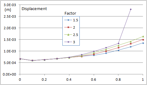
Figure 7: The displacement of the indicator point shows that the safety factor should be between 2.5 and 3. |
The calculation can be refined within the last bounding interval. In the following table the result for
a final calculation is given in which the interval from 2.5 to 2.6 has been assigned to the reduction factor variation with a
step of 0.02. For the reduction factor 2.56, the calculation has not converged up to the last step of excavation (Load ratio 1).
Hence, the safety factor is between 2.54 and 2.56.
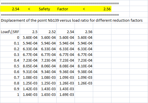
Figure 8: The calculation for the reduction factor 2.56 has not converged up to the last load increment: the Safety Factor is smaller than 2.56 |
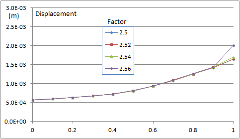
Figure 9: The displacement of the indicator point shows that the safety factor should be between 2.54 and 2.56 |
It can be noted that the interval between 2.54 and 2.56 found in this way for the safety factor is very close to the value 2.51
found by the first method. This is due to the very simple geometry of the problem (triangular bloc). For more complex geometries
the results can differ more.
Note also that in Disroc the "Shear Strength Reduction Method" can be applied without difficulty to continuous materials
in order to analyze, for instance, the soil slope stability and determine the safety factor for embankments.
Complementary documents:
- Slope Stability by Shear Strength Reduction Method
paper