|
|
DISROC Examples |
|
| DISROC 5 - Example: |
Other Examples |
Tunnel in anisotropic viscoplastic rockmass:
effect of rock creep on the lining
The model ANELVIP (31430) of the materials catalog of Disroc
covers viscoplastic materials with anisotropic creep properties.
It can well represent the viscous behavior of some varieties of rocks at great depth like rock salt (isotropic) or
schist (anisotropic). Plastic deformation as well as anisotropic elastic behavior can well be considered in this model.
But in the following example, plastic strain, occuring more in the excavation phase, is not considered and the elasticity
is assumed to be isotropic, as well as the ground stresses. The objective is to focus on the anisotropic creep and convergences
after excavation and due to the anisotropic viscous deformation of the rock.
A stress threshold is taken
into account for this material as well as a strain hardening which makes that the viscous strain rate decreases with
time under a constant applied stress. Both the stress threshold and the strain rate for a stress applied in different
directions of the material can be anisotropic. The model offers different options of anisotropy of the stress
threshold and/or of the creep strain rate in order to best fit the observed properties of the material.
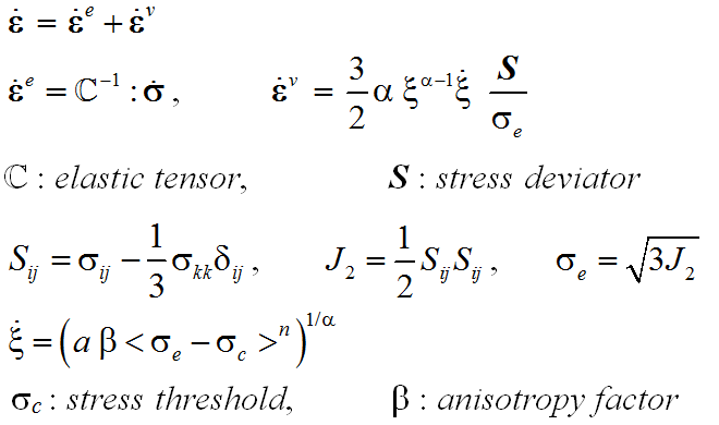
Constitutive Equations |
|
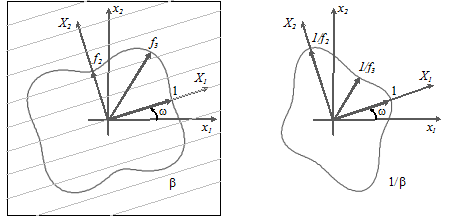
Briefly speaking, the stress threshold for a uniaxial stress in a direction X2, representing the axis of transverse isotropy
of the material, can be f2 times smaller than the threshold in the lateral directions, and the creep rate can be
beta times greater than in the lateral directions. The direction of these material axes makes and angle omega with the coordinates
axes.
A tunnel with a circular section is considered in this kind of anisotropic viscous rock formation. The in situ stress is supposed isotropic.
The state of the stress and displacements around the tunnel immediately after excavation is the same that in an isotropic material
(because elasticity is supposed isotropic). Then starts the creep which induces anisotropic strains and so anisotropic stress redistribution
and convergences around the tunnel.
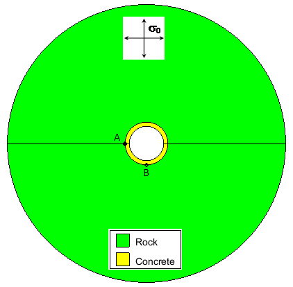 Fig.2a: Circular tunnel with concrete lining in a viscoplastic rockmass with isotropic far-field stress sigma_0
|
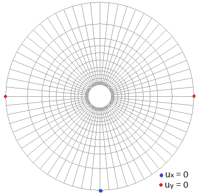 Fig.2b: FEM mesh for numerical simulations with boundary displacement conditions
|
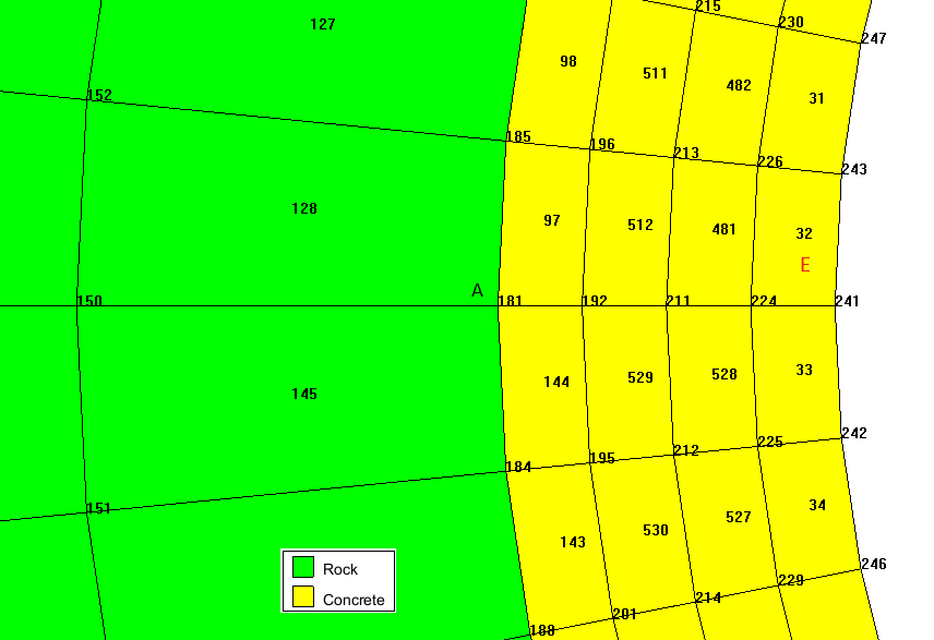 Fig.3: Details of FEM mesh for the lining
|
The following figures show the stress field immediately after excavation far a in situ stress equal to 10 MPa. The hoop stress at the wall of the tunnel is the same all around the tunnel because of the isotropic elasticity, and is equal to two time the far-field stress (small differences are due to the coarse mesh).
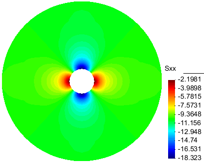 Fig.4a: Contour of Sigma_xx at t=0
|
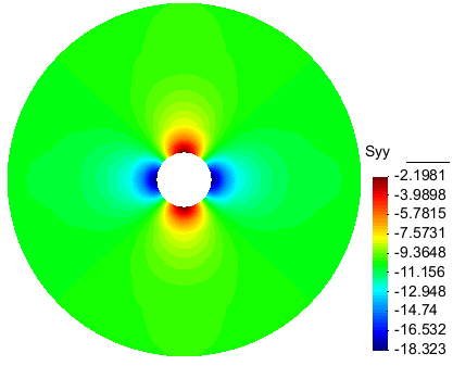 Fig.4b: Contour of Sigma_yy at t=0
|
The free convergence of the tunnel is modeled first. It leads to a new state of stresses which has no more the axial symmetry around the tunnel
axis because of the anisotropic creep of the rockmass. The convergence (radial displacement) at the points A and B on the
wall of the tunnel without lining (see Fig. 2a), are presented on Fig.4a. The difference of convergences leads to a flattening
of the section as shown in the following figures (see Fig.6). The convergence rate remains decreasing if the parameter alpha in the constitutive
model is smaller than one (the simulation was performed with alpha=0.5) whereas a steady state of stress with a constant
(asymptotic) convergence rate would be reached for alpha=1 (Norton-Hoff model).
The evolution of the hoop stress is also different at the points A and B as presented on Fig. 5b.
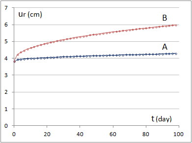 Figure 5.a: Free convergences at the points A and B
|
 Figure 5.b: Evolution of the hoop stress at the points A and B
|
The contours of Sigma_xx and Sigma_yy at the end of simulation are presented on Figure 6. Compared to the Fig. 4, they show well the effect of anisotropic creep on the stress redistribution in the rockmass.
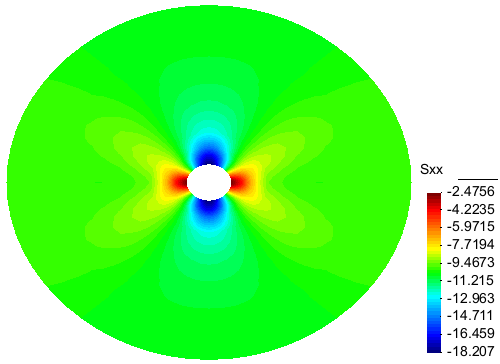 Figure 6.a: Contour of Sigma_xx after 3 months
|
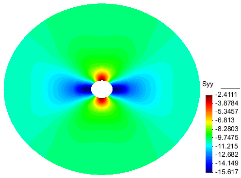 Figure 6.b: Contour of Sigma_yy after 3 months
|
To analyze the effect of viscoplastic deformation of the rockmass on the lining, it is supposed that the lining is placed in the tunnel immediately after excavation. The convergence of the tunnel is no more free and induces stresses in the lining. The Mises equivalent stress is chosen to represent the state of stress in the concrete. The Fig. 7a shows that this stress is zero initially in the concrete when the lining is placed in the model immediately after excavation. Then, after 3 months convergence with an isotropic creep behavior assigned to the rockmass, the stress in the lining attains a uniform value along the lining about 1.4 MPa (Fig. 7b).
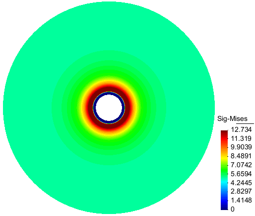
Figure 7a: Contour of the Mises equivalent stress immediately after the lining is placed in the tunnel: the stress is zero in the lining |
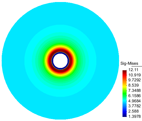
Figure 7b: Contour of the Mises equivalent stress after 3 months of convergence for isotropic creep of rockmass: the stress is uniform along in the lining |
When an anisotropic creep for the rockmass is modeled then the resulting stress is no more uniform in the lining. An anisotrpic creep was supposed for the rockmass with the creep rate in the vertical direction 4 times greater than in the horizontal direction but with an average value equal to the value for the isotropic creep considered in the previous case. The Fig. 8a,b show the Mises stress and the hoop stress in the lining after 3 months creep. Their minimum and maximum values are obtained at the points A and B (located on Fig.2a). The maximum Mises stress value, about 15 MPa, is ten times greater than the value obtained in the isotropic case! The compressive hoop stress at the same point reaches 17 MPa after 3 months convergence (Fig. 9), also about ten times greater than in the isotropic case (1.8 MPa).
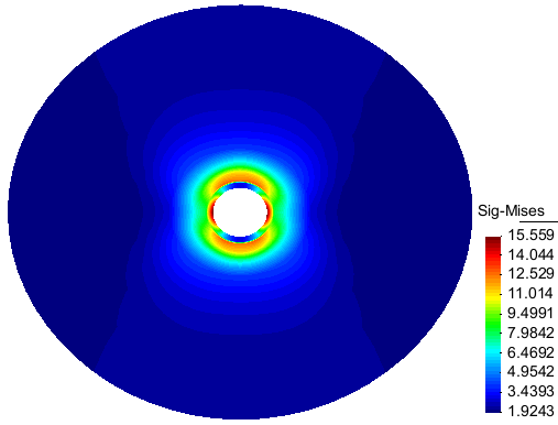 Figure 8a: Contour of the Mises equivalent stress after 3 months convergence for anisotropic creep
|
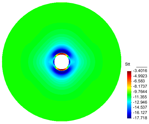 Figure 8b: Contour of the hoop stress after 3 months convergence for anisotropic creep
|
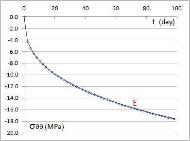
Figure 9: Evolution of hoop stress in the lining near the point A (in the element E, 32, see Fig. 3) |
In a new simulation with a 33.75° rotation of the axes of material anisotropy with respect to the coordinates axes is introduced in the constitutive model (omega=33.75, see Fig. 1). The Fig.10 shows the effect of this rotation on the deformation axes of the tunnel.
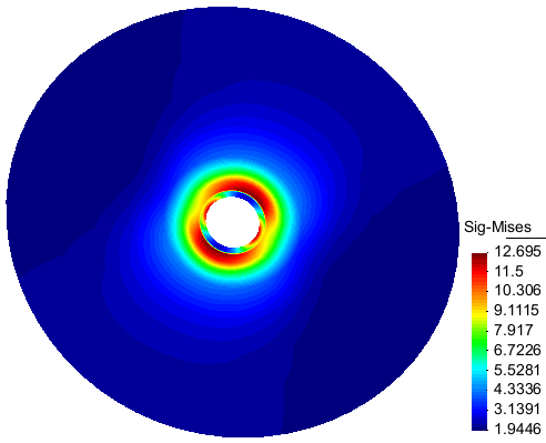
Figure 10a: Contour of the Mises equivalent stress with a 34° rotation of the material axes of anisotropy |
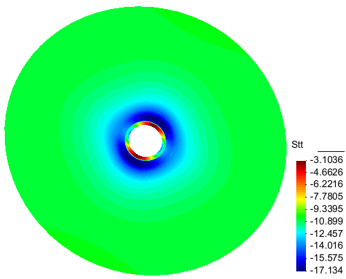
Figure 10b: Contour of the hoop stress with a 34° rotation of the material axes of anisotropy |
The anisotropic viscous deformation of the rockmass thus induces non uniform stresses in the lining the maximum value of
which exceeds considerably the average value obtained by an assumption of isotropic creep.
Disroc allows to analyzing these stresses.
As an extension of this study, it is possible to take into account the anisotropy of the elastic parameters of the of the rockmass
(models 31300 or 31400 of the Catalog), its plasticity (model 31410 of the Catalog which can be extended to
anisotropic plastic criterion) as well as an anisotropic state of the ground stress.
On the other hand, the materials catalog of Disroc is sufficiently rich to allow introducing in the model specific structural
elements like HDC Elements (High Deformable Concrete) used for lining design in squeezing rocks. The interface between the concrete
ring and the rock can be, if necessary, modeled by Joint Elements (the line 'Fill' in Fig.11). A rich variety of constitutive models for
Joint Elements are available in Disroc allowing to model different configurations of contact conditions or of filling materials in the
interface (See the non linear interface models 21200 or 21220 in the Catalog).
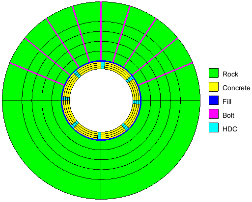
Figure 11: A complete model of rock support for tunnel in squeezing rockmasses including HDC Elements (Highly Deformable Concrete) and rockbolts |
Finally, very advanced rockbolt models are available in Disroc which could be used, if needed, in order to have a complete model of rock support (see the model 41110 in the Catalog).
Complementary documents:
- Analysis of underground excavations in viscoplastic rock formations
paper
- Creep parameters of rock salt
paper
- Ellipsoidal anisotropy for the elastic behavior of rockmasses
paper
- Time-Dependent Modeling of Tunnels in Squeezing Conditions
paper