|
|
DISROC Examples |
|
| DISROC 5 - Example: |
Other Examples |
Effect of grain boundary cracking on damage and cyclic fatigue of polycrystalline salt
The mechanical behavior of salt rock is studied for its applications to nuclear waste
disposals, oil and gas storage and, more recently, compressed air energy storage (CAES)
in salt caverns. Salt rock has both a viscoplastic behavior and a damage (cracking)
behavior which are strongly coupled in that the cracking of salt rock is very sensitive
to strain rate.
A way to understand and study this phenomenon is to consider the polycrystalline nature
of salt rock. The effective properties and non linear behavior of polycrystalline aggregates which cover metal alloys and crystalline were studied extensively during last decades by various methods. Observational and experimental methods as well as various theoretical investigations by upscaling methods provide an overview of this behavior which could be deepened and completed by a numerical modeling investigation. In many polycrystalline aggregates, grain boundaries play an important role in deformation mechanisms and sometimes have dominant or determinant effects on the overall properties of the aggregates.
Disroc offers great facility for analyzing polycrystalline behavior especially related
to grain boundary effects. Indeed:
- Disroc makes it possible to easily create complex geometries of polycrystalline aggregates with grain boundaries modeled as joint or interface elements,
- The catalog of materials of Disroc includes advanced constitutive models for the elastoplastic, viscous and damage behavior of interfaces,
- Disroc includes "Homogenization" as a standard function which consists in applying specific boundary conditions to the Representative Elementary Volume (REV) and to the calculation of the macroscopic (homogenized) quantities of stress and strain (total, elastic, plastic.). The contributions of the various components (bulk material and interfaces) to macroscopic stress and strain quantities are calculated separately.
The following example in which grain boundaries play a determining role is taken from the doctoral work of Cheng Zhu (Georgia Tech, 2016) [1]. The numerical simulations of this example were carried out with Porofis, a research code derived from the first versions of Disroc.
Cyclic fatigue of polycrystalline halite aggregates [1]:
Around underground caverns in the salt geological layers used for oil and gas storage,
rock salt experiences cyclical loads due to storage-withdrawal cycles. In this evaporitic
rock, made up of halite crystals, the grains (halite crystals) have random crystallographic
orientations. The plastic deformation of crystal grains, due to sliding on crystallographic
systems, is therefore very heterogeneous. From this heterogeneity and the incompatibility
of the plastic strain field result internal stresses in the aggregate which can cause its
cracking and its damage. During a cyclic loading, the plastic strain accumulates after each
cycle and increases the internal stresses. Due to the weak cohesion of the grain boundaries,
the cracks propagate preferentially at these boundaries (intergranular damage).
To investigate numerically the damage process, first a REV was built for the aggregate
from digital image analysis of an Electron Back Scatter Diffraction map of a salt
specimen (Fig. 1). The grains shape and crystallographic orientation were inspired from
this image to build the REV (Fig. 2).
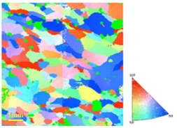 Fig.1: Electron Back Scatter Diffraction map of a salt specimen used for geometry definition [1]
|
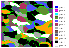 Fig.2: Grain geometry of the REV created for a salt specimen. Grain numbers refer
to grain orientations [1]
Fig.2: Grain geometry of the REV created for a salt specimen. Grain numbers refer
to grain orientations [1]
|
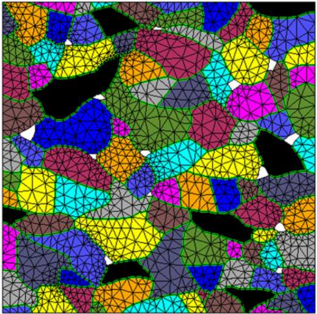
Then a Finite Element mesh was created by the Post Processor GID (Fig. 3). In this REV, each color corresponds to a crystallographic orientation of the grain. Overall, 12 different orientations were considered. Next, the Discrac module from Disroc was used to transform all grain boundaries into joint elements (Fig. 4).
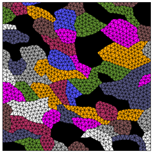
Fig.3: The standard Finite Element Mesh created for the REV |
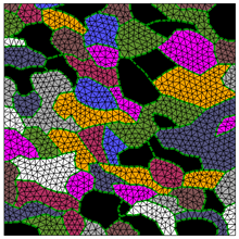
Fig.4: Mesh enriched with joint elements on the grain boundaries |
The grains have viscoplastic behavior with isotropic elasticity and crystalline viscoplasticity. Their constitutive model is as follows:
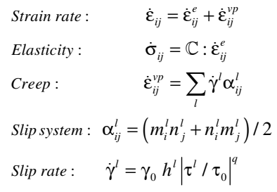
Chrystalline viscoplastic constitutive model |
In these equations nl and ml are the unit vectors which
respectively define the normal to the slip plane and the slip direction of the slip
system number l, τl is the shear stress on the slip system,
nl = ±1 is the sign of τl and γ0 , τ0
and q constant parameters.
Compression of the aggregate induces elastoplastic deformation of the halite crystals.
The crystallographic orientation is heterogeneous and due to this heterogeneity, there
is an incompatibility of the plastic strain of adjacent crystals in the aggregate.
The incompatibility of the plastic strain must be compensated for by elastic strains and
thus induces internal stresses. When these internal stresses exceed the strength limit
of the material cracks appear in the aggregate. The grain boundaries are weakness zones
and cracks appear preferentially at these interfaces.
A Cohesive Zone Model for interfaces called "CZFrac" is available in Disroc (model 21510,
[4]). The propagation of fractures is simulated with this model as a damage process in
the interface. The damage variable D varies from 0 to 1, with D=0 for the intact state
and D=1 for the completely damaged state. The interface has, in the initial state, a
cohesion which decreases with the damage. At the end of this process, there remains
a pure frictional contact between the two faces of the interface. Thus the initial bonded
interface turns into a fracture (Fig. 5).
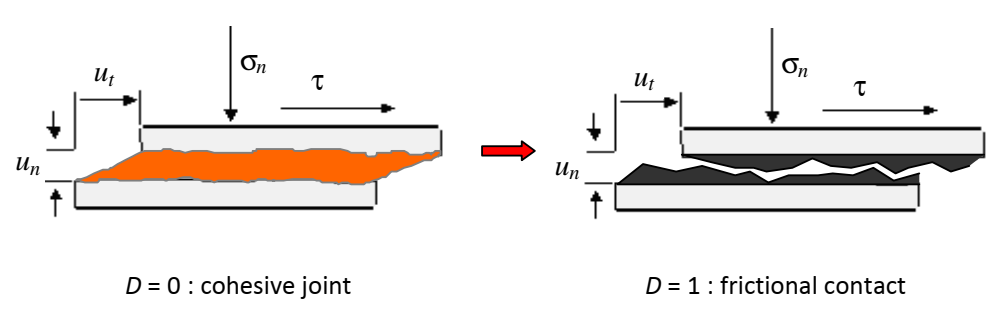
Fig. 5 : The damage process changes a cohesive or bonded interface to frictional contact surface [4] |
The damage begins when the state of stress reaches the strength criterion of the interface. The strength criterion of the CZFrac model has a hyperbolic form in the (σn , τ) plane where τ and σn are the shear and normal stress on the interface (Fig. 6). The hyperbola is defined with three parameters related to the three physical parameters which are the tensile strength of the interface σR, the cohesion C and the asymptotic friction angle φ. These parameters vary from their initial values for D=0 to the final residual values for D=1 as can be seen in the Figure 6. This evolution is defined by two functions g(D) and h(D) which depend on a parameter β controlling the brittle to ductile paste of the damage process. The main constitutive equations defining the initial strength criterion F0 and its residual value Fr of the CZFrac model are as follows:
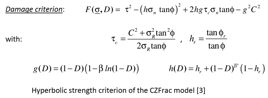
Hyperbolic strength criterion of the CZFrac model [4] |
A simplified version of this model with constant friction angle (function h remaining constant) was used for the simulations in this study.
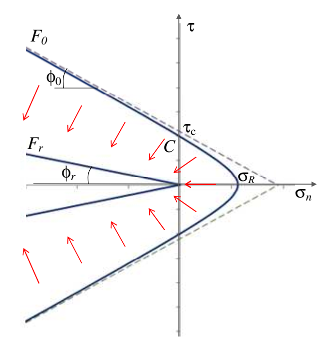
Fig. 6 : The strength criterion of the CZFrac model in the (σn , τ) plane with F0 for the initial state and Fr for the damaged residual state [4] |
When a compressive load is applied on the REV, viscous deformation occurs in the grains and induces shear and in some cases tensile stresses on the grain boundaries. Fig. (7) shows the deformed shape of the REV which reveals open cracks developed on some grain boundaries. The presence of these cracks decreases the effective elastic stiffness of the aggregate.
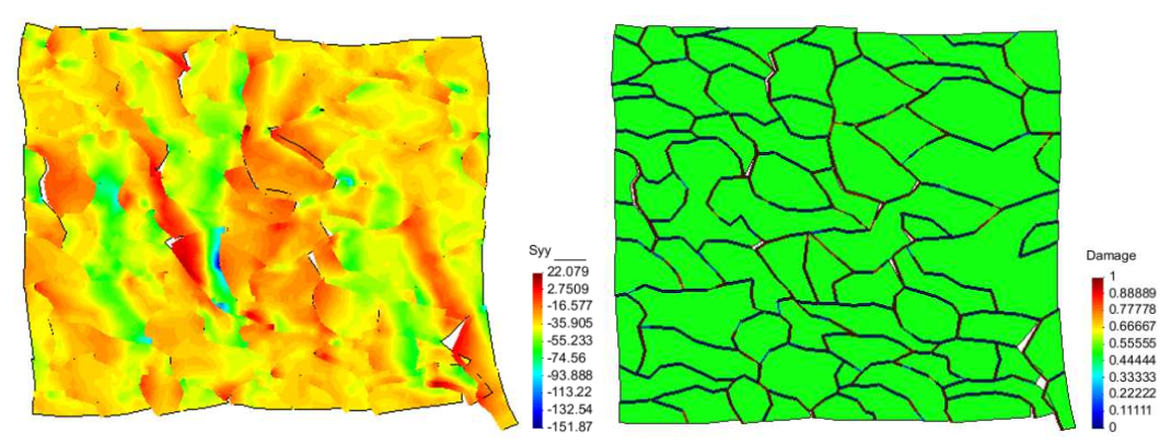
Fig. 7 : Deformed shape of the REV showing open cracks with the vertical stress filed (left) and the damage on grain boundaries (right) |
To model the cyclic fatigue of the polycrystal, cyclic compressive loads were applied to the REV with three different stress amplitudes and periods. Figure 8a shows the stress-strain curve of one of these tests. The effective elastic parameters of the aggregate were calculated at each cycle by the homogenization functions of Disroc. The detail of an unloading path to measure the Young's modulus at the end of a cycle is shown in the Figure 8a. The homogenized stiffness of the aggregate as well as its strength parameters decreases with the number of cycles. Figure 8b shows the decrease of the effective Young's modulus of the REV with the number of cycles. The simulation of cyclic loads with different periods and amplitudes allowed to build a fatigue model for the aggregate [1],[2],[3].
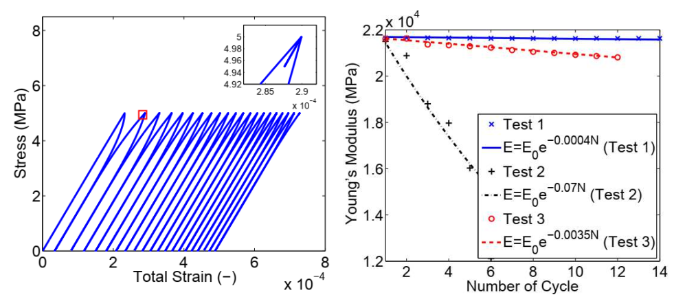
Fig. 8: Left: stress-strain for test 1, Right: Variations of the polycrystal Young's modulus with the number of cycles in three tests corresponding to different cycle period and stress amplitudes |
This analysis was then deepened by considering the possibility of crack propagation inside the grains (intragranular damage). Discrac module of Disroc makes it possible to place a family of joint elements on all the sides of the surface elements (triangles in this example) (Fig. 9a). This family of joints is also modeled by cohesive zone CZFrac model but with stiffness and strength values different from the family located on grain boundaries. Then, depending on the properties of two families of joints and also on the angle of incidence of the crack encountered at the grain boundary, the crack can penetrate into the grain or spread on the grain boundary (Fig. 9b). An example of these two modes of crack propagation at an interface in a heterogeneous material modeled with Disroc can be seen here [5]
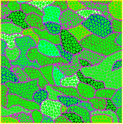
Fig. 9a: An additional family of joint elements placed inside the grains (all the sides of triangular elements) in order to allow intragranular crack propagation. |
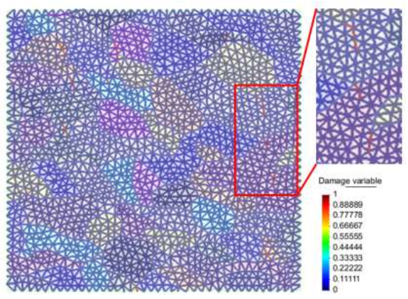
Fig.9b. The detail of the figure shows that in some cases the crack has penetrated the grain |
Finally this analysis could be applied to crushed salt. This material used also in nuclear waste disposal projects is not strictly speaking a polycristal, but can be modeled as an aggregate of grains which are in contact with each other. The aggregate also contains empty spaces. The Figure 10 show the mesh that could be created to model the crushed salt in which the white space represents the void between grains. Some aspects of the mechanical behavior of the crushed salt was also studied in this was by numerical modeling [1].
|
| Fig. 10. Finie Element Mesh enriched with joint elements for crushed salt. The grain colors refer at grain orientations, the contact surfaces between grains are modeled by joint elements and the white space between the grains corresponds to the empty space in the crushed salt [1]. |
References
[1] Cheng Zhu, (2016). Microstructure-Based Modeling of Damage and Healing in Salt Rock
with Application to Geological Storage. PhD thesis, Georgia Institute of Technology
May 2016.
[2] Zhu, C., Pouya, A., Arson, C. (2016). Prediction of viscous cracking and cyclic
fatigue of salt polycrystals using a joint-enriched finite element model.
Mechanics of Materials, 103, 28-43.
[3] Pouya A., Zhu Cheng, Arson Chloé (2016). Micro-macro approach of salt viscous fatigue under cyclic loading.
Mechanics of Materials 93 (2016) 13-31.
[4] Disroc, Catalog of Materials, Fracsima 2020, http://www.fracsima.com/DISROC/Materials-Catalog.pdf
[5] Fracsima,
Fracture propagation in heterogeneous materials
(http://www.fracsima.com/DISROC/Examples/Beef/Beef-Fracture.html)